
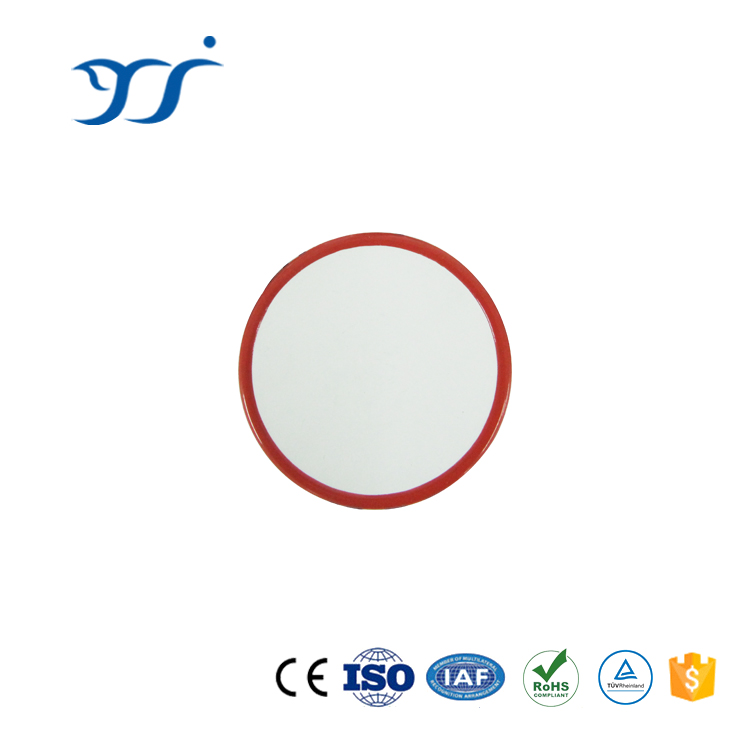


Rectifier diode Chip
Rectifier Diode Chip
The rectifier diode chip manufactured by RUNAU Electronics was originally introduced by GE processing standard and technology which compliant of USA application standard and qualified by worldwide clients. It’s featured in strong thermal fatigue resistance characteristics, long service life, high voltage, large current, strong environmental adaptability, etc. Every chip is tested at TJM , random inspection is strictly not allowed. The consistency selection of chips parameters is available to be provided according to application requirement.
Parameter:
| Diameter mm |
Thickness mm |
Voltage V |
Cathode Out Dia. mm |
Tjm ℃ |
| 17 | 1.5±0.1 | ≤2600 | 12.5 | 150 |
| 23.3 | 1.95±0.1 | ≤2600 | 18.5 | 150 |
| 23.3 | 2.15±0.1 | 4200-5500 | 16.5 | 150 |
| 24 | 1.5±0.1 | ≤2600 | 18.5 | 150 |
| 25.4 | 1.4-1.7 | ≤3500 | 19.5 | 150 |
| 29.72 | 1.95±0.1 | ≤2600 | 25 | 150 |
| 29.72 | 1.9-2.3 | 2800-5500 | 23 | 150 |
| 32 | 1.9±0.1 | ≤2200 | 27.5 | 150 |
| 32 | 2±0.1 | 2400-2600 | 26.3 | 150 |
| 35 | 1.8-2.1 | ≤3500 | 29 | 150 |
| 35 | 2.2±0.1 | 3600-5000 | 27.5 | 150 |
| 36 | 2.1±0.1 | ≤2200 | 31 | 150 |
| 38.1 | 1.9±0.1 | ≤2200 | 34 | 150 |
| 40 | 1.9-2.2 | ≤3500 | 33.5 | 150 |
| 40 | 2.2-2.5 | 3600-6500 | 31.5 | 150 |
| 45 | 2.3±0.1 | ≤3000 | 39.5 | 150 |
| 45 | 2.5±0.1 | 3600-4500 | 37.5 | 150 |
| 50.8 | 2.4-2.7 | ≤4000 | 43.5 | 150 |
| 50.8 | 2.8±0.1 | 4200-5000 | 41.5 | 150 |
| 55 | 2.4-2.8 | ≤4500 | 47.7 | 150 |
| 55 | 2.8-3.1 | 5200-6500 | 44.5 | 150 |
| 63.5 | 2.6-3.0 | ≤4500 | 56.5 | 150 |
| 63.5 | 3.0-3.3 | 5200-6500 | 54.5 | 150 |
| 70 | 2.9-3.1 | ≤3200 | 63.5 | 150 |
| 70 | 3.2±0.1 | 3400-4500 | 62 | 150 |
| 76 | 3.4-3.8 | ≤4500 | 68.1 | 150 |
| 89 | 3.9-4.3 | ≤4500 | 80 | 150 |
| 99 | 4.4-4.8 | ≤4500 | 89.7 | 150 |
Technical specification:
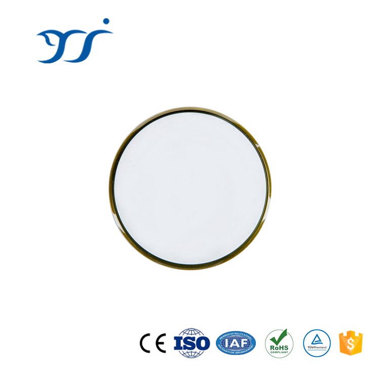
RUNAU Electronics provides power semiconductor chips of rectifier diode and welding diode.
1. Low on-state voltage drop
2. The gold metallization will be applied to improve the conductive and heat dissipation property.
3. Double layer protection mesa
Tips:
1. In order to remain the better performance, the chip shall be stored in nitrogen or vacuum condition to prevent the voltage change caused by oxidation and humidity of molybdenum pieces
2. Always keep the chip surface clean, please wear gloves and do not touch the chip with bare hands
3. Operate carefully in the process of use. Do not damage the resin edge surface of the chip and the aluminum layer in the pole area of the gate and cathode
4. In test or encapsulation, please note that the parallelism, flatness and clamp force the fixture must be coincide with the specified standards. Poor parallelism will result in uneven pressure and chip damage by force. If excess clamp force imposed, the chip will be damaged easily. If imposed clamp force is too small, the poor contact and heat dissipation will affect the application.
5. The pressure block in contact with the cathode surface of the chip must be annealed
Recommend Clamp Force
| Chips Size | Clamp Force Recommendation |
| (KN)±10% | |
| Φ25.4 | 4 |
| Φ30 or Φ30.48 | 10 |
| Φ35 | 13 |
| Φ38 or Φ40 | 15 |
| Φ50.8 | 24 |
| Φ55 | 26 |
| Φ60 | 28 |
| Φ63.5 | 30 |
| Φ70 | 32 |
| Φ76 | 35 |
| Φ85 | 45 |
| Φ99 | 65 |